|
|
|
|
|
|
|
|
|


Инструкции к репитерам |
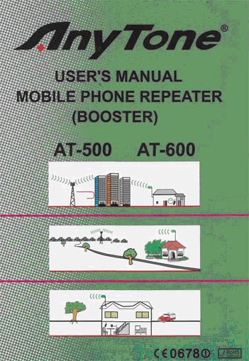
Users manual mobile phone repeater ANYTONE
Getting Acquainted AT-500 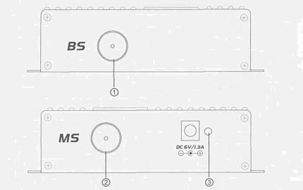
1 .BS: connect outdoor antenna 2.MS: connect indoor antenna 3.power/signal strength two color indicator: green light on means power on, red light on or flash means signal well received, the communication is smooth. 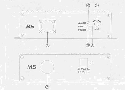
AT-600 1 .BS: connect outdoor antenna 2.MS: connect indoor antenna 3.POWER:Power indicator, light on means power on, light off means power off. 4.SIGNAL:Signal strength indicator, light on means antenna is installed correctly, light off means user need to change the outdoor antenna install address/direction/angle until light on. 5.MLC:Manually adjust electrical level. Default setting of electrical level is maximum, can be reduced by clockwise adjust (total 10rounds adjustable, decreased by 1dB per round). After installation or if the communication is abnormal, user can adjust output electrical level clockwise to make the indicator light flash, it is in best working status when light flash. 6.ALARM:The indicator lighting on means that the output power is too high or system self-exciated occurs.User need to adjust MLC until the indicator off (Normal status: Power and Signal lights on,Alarm off). Standard Accessories 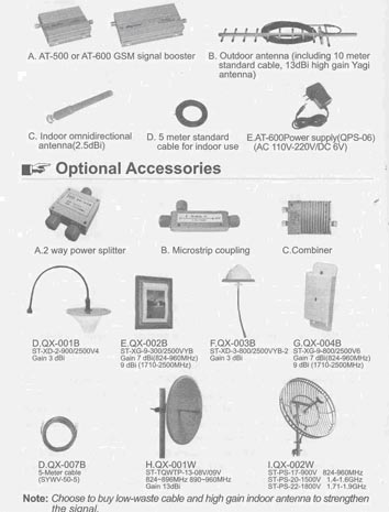
Pictures of Structure 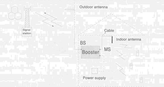
1. Indoor coverage is about 200m2 with simple building structure for AT-5C Indoor coverage is about 300m2 with simple building structure for AT-6C 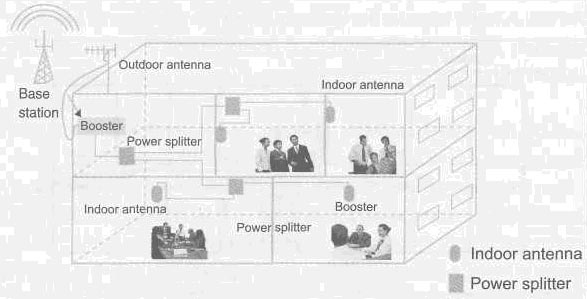
Please install bv the wav as fiaure 1 shows. 2. Strong signal situation outside, weak signal situation inside of the building caused the shielding of buildings. Please install with the optional accessories by the way as figure 2 shows. 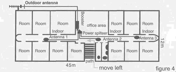
3. Strong signal situation outside, very weak situation inside of the building caused the shielding of buildings. Please install withytnyToneseries mini repeater and optional accessories by the way as figure 3 shows. Note: Avoid L mode coverage before you choose the installing position of indoor antenna. Take example, the indoor antenna2 installed on the walkway exit had better move left, in order to make the walkway within the coverage of antenna. Installation For the best performance choosing optimal installing place is very important to the whole project. A. Check & measurement with measuring instrument This enables you to determine how signal levels can be received indoor and outdoor by means of Spectrum analyzer or Field strength meter. B. Status check with cellular phone Checking the operating status with a cellular phone is one of the simplest methods. Testing by your cell phone is not so precise, compared with Spectrum analyzer and much slower with the calculate speed. In order to get more reliable data, you will have to stay for a while at every place you would like. Normally, it would get better result to make the outdoor antenna face the base station tower. Installation can only be processed where there is one or more marks showing on your cell phone, amplifying effect would be better if there are 2 or more marks, while the effect would be a little worse if there is only one mark showing on your mobile phone. С Outdoor antenna installation 1. On the top of building, select safe position with strong signal(2 bars more), where it is easy to install, assemble and maintain the outdoor antenna. 2. Keep the outdoor antenna away from high frequency area, metal net, high voltage cable or transformer, be aware of avoiding the thunder and lightning. 3. Adjust the outdoor antenna direction is mandatory, use the LED level meter or instrument to set it towards the direction where best intensity is sensed. Tune the elevation angle and azimuth angle, It must point to the direction of provider whose base station is locked nearthest.(AT-600 only) 4. Notice: Make sure the distance between the indoor antenna and outdoor antenna is more than 10m, in order to avoid self-oscillation, which is caused by the feedback to the outdoor antenna of signal transmitted by indoor antenna. Normally, the outdoor antenna should be 5-6m higher the roof and the indoor antenna should be installed to the back side of outdoor antenna. After the work above, you can fix the outdoor antenna not so fast, because you may have to do some adjustment after installing the indoor antenna and repeater body. D. Installation of repeater body To establish the repeater body, please do as the following picture shows. 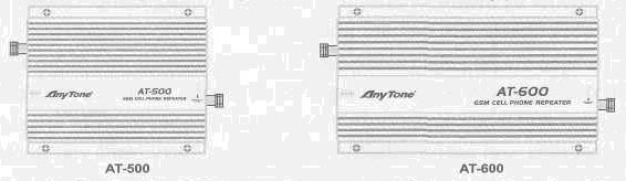
Fasten the body with 4 M4 expansion screws. Make sure there is at least 50mm around the body, for the need of aeration and power plug. Make sure the place is dry and drafty and far away from high temperature, heat source and dust. After fixing the body, you can plug the N-J connector of outdoor antenna cable into the BS interface and plug the N-J connector of indoor antenna cable into the MS interface. Meanwhile, please connect the indoor antenna and confirm all the connections are perfect. You have to fasten the cables and connectors to make sure no short circuit and open circuit occurs, otherwise the working efficiency would much decrease and the body may get broken. E. Indoor antenna installation The place of indoor antenna is much important to the work efficiency. Unreasonable placing may result in self-oscillation in system. It is important to easy operate and maintain the indoor antenna at a beautiful, practical and seclueded position. Put the indoor antenna where you imagine. Test the indoor field-strength distribution in every corner of the room by the similar way of testing outdoor intensity. You can test by field-strength analyze or mobile phone, and adjust the position until the distribution of field strength is reasonable in each room. Otherwise the position of the antenna should re-adjust. If it stays the same after doing that, you must choose another model Anyопе series or make a special ODM order. You can also install more pieces of repeater for expanding the coverage. When you confirm the position of indoor antenna, you can use bracket and screws we offer to fasten and fix the indoor antenna. Normally, you can fix it on the wall, pillar and ceiling, etc. The axes of indoor antenna must be faced up and faced down, and it should be placed at least 2m over the ground. Please see the right figure. Notice: You must examine all the items showed above, then you can turn on power only. When it finished fix ofAT-500, The power indicating light show red after turn on power, If so, it mean the machine works normal. When it finished fix ofAT-600, The power indicating light show yellow (Red and Green flashing) after turn on power, If so, it mean the machine works normal, better signal, reach to coverage scope. If the light showed only Red, the machine works normal ,the signal weak, coverage scope can't reach very well, adjust the position of the antenna. You also need to wrap up the connector of outdoor antenna with rubberized fabric to prevent moisture (or rain) passing through the cable inside the small casket of outdoor antenna. Also we need to prevent rainwater passing into the room from the cable. After finishing the work for waterproof, you can check again the working situation of outdoor antenna by indicating light and then fasten the outdoor antenna. Finally, make sure the distribution of cables is fastened and tidy to the surroundings. Now, enjoy the AT-500 or AT-600 for communication! More expanded indoor coverage is desired There are optional accessories of the equipment, you can change the outdoor antenna as QX-001W, QX-002W etc, and change the indoor antenna as QX-002B, QX-004B etc. They can expand the coverage though the superior gain, compared with convenient antennas. Warnings The repeater is designed to reply simultaneously to broadband frequencies, as a broad repeater. The following situations require careful installation: 1) Under more than two service providers the existing frequency band of the repeater to be installed, if a certain base station is located within tens of meters, while the other stations are at several kilometers, signal from the nearby station are much more dominant. So, ALC operates automat¬ tidally. And in this situation, the attenuator operates at up to 35dB.For this reason, as signals from a long-distance station decrease the gain of the repeater, the maximum gain of 50dB(AT-500) or 60dB(AT-600) is unavailable; It may fail to relay. Ergo, in such a case, use only a directional antenna (Yagi antenna, etc.) to install it in the opposite direction to the nearby station, in order to minimize the signals exchanged with the station. You also can select other Aпуtопе repeaters with low gain and power. 2) Since this equipment performs high-gain amplification, if the outdoor antenna is closed to the indoor one, or the two antennas are adjacent, the RF signal may be feed-backed and abnormal self-oscillation may occur, which may cause serious damage to the cellular phone, even worse, to the base station. To be careful. The most reliable method is to measure and check the condition with Spectrum analyzer. 3) When connecting N-J connector to repeater N-K connector, you need to aim and push with a bit strength. When feeling tight, please use one hand to hold tightly the back part of the cable connector; and use another hand to fasten the nut. In this process, the nut goes forward 5mm and 4 circles around. So do with other connections. 4) Make sure all the crooks of cables are flexible and more than 75mm in radii of the flexure. Rigid crooks would increase the lose of cables. 5) Put the cable on the wall or windows and dig one 25mm hole to let the cable and its connectors through. 6) The outdoor antenna cable should face down and far away from the small casket of outdoor antenna to prevent the rainwater assemble and flow into the casket. 7) Make sure the indoor antenna is at least On far away from the outdoor antenna and be placed at the back side of outdoor antenna 8) Note: Connect cables of outdoor antenna with BS interface of body and cable of indoor antenna with MS interface. 9) Fasten all connectors before wrapping up with rubberized fabric. 10) Never install the antenna in the places where the risk of a fire is highly, or where the mobile blocker is installed. Trouble Shooting The power LED in the front of the equipment doesn't light up, although the equipment is completely installed and switched ON. Check whether the power is normally supplied in the AC power source outlet. The PWR LED lights up normally, but the LED level meter doesn't light up at all. (AT-600 only) Check whether the outdoor antenna is correctly connected. The signal level is not displayed on the cellular phone, although the power LED lights up normally. Check whether the power indicating light turn to yellow or not if so, it mean the machine works normal, better signal. (AT-600 only) b. Check whether the antenna cable (coaxial cable) or the connector is correctly connected. When signals are very weakly received from the base station, normal reception is unavailable even outdoor (where the outdoor antenna is installed), check it with the cellular phone or measuring instrument. If the signals are poor, adjust the position of the antenna. Nevertheless if they are poor, use the optional antenna to increase the gain of the antenna. Self-oscillation occurs. May due to the short distance between the outdoor and indoor antenna, Please change the installed places of the antennas in order to maximize the distance between them. The signal is strong in some places and weak in some places. That means power is distributed unevenly, due to something wrong with the indoor distribute. If the signal in several positions is weak, you should distribute the signal like figure 3. The signal is weak anywhere. That means the power and gain of repeater is not enough, changing a high one or multi-combination. Performance is falloff and where to repair As advanced techniques are required to operate this equipment, a non-discretionary disassembly or modification may not only give failure to the other communication, but may also cause falloff of in durability or perfor¬mance. Thus, always contact the specified customer service center for appropriate procedures. Notice: 1. Installation is prohibited in the immediate proximity of the BTS. 2.The repeaters should be installed by professional workers authorised by the mobile operator. |
|||||||||||||||||||||||||||||||||||||||||||||||||||||||||||||||||||||||||
|
|
||||||||||||||||||||||||||||||||||||||||||||||||||||||||||||||||||||||||||

|
info@viam-radio.ru (495) 997-63-68
VIAM-RADIO.RU © Все права защищены. При использовании материалов сайта ссылка наwww.viam-radio.ru обязательна. Не является офертой. |